Technical Specifications for the Installation of Optic
Fiber Cabling
Version 1.1, March 1997
1. Introduction
Information Systems and Services (ISS) currently specifies the installation and use of multimode optic fiber cable to support a variety of communication services on the GW campus. This document will expand the scope of optic fiber technical specifications to include both single-mode and multimode optic fiber cable.
The standard optic fiber communications cabling specified for use on the GW campus shall be of a specific type and must be installed according to the following standards. The standards for optic fiber communications cable are more restrictive than those normally encountered for twisted-pair copper voice communications. In general the requirements include :
- A specified cable type
- Restricted cable topology
- Maximum end-to-end circuit length
- Specific handling and installed cable protection
- Specific outlet types and placements
- Compliance testing of installed cabling
2. General
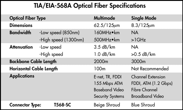
Optic fiber cables shall be installed in unbroken segments from central utility closets to individual workstation locations. In the utility closets optic fiber cables shall be terminated on patch panels in 568SC adapters (couplers) designated by color. A 568SC connector consists of two color coded SC-type connectors joined to form a mated duplex pair. Beige colored connectors and adapters are specified for 62.5/125 micron multimode optic fiber. Blue colored connectors and adapters are specified for 8-10/125 micron single mode optic fiber.
Optic fiber adapter panels may not be used for mixed single and multimode usage. Existing connecting hardware utilizing ST-type connectors, biconic connectors, and mini-biconic (datakit) connectors are grandfathered and will not be replaced with SC-type connectors. All new optic fiber cables will terminate in color coded 568SC connectors and adapters.
At each workspace location multimode optic fiber cables shall be terminated in a wall mounted TIA/EIA 568B compliant communications outlet from specified manufacturers capable of terminating a minimum of two fibers into a beige 568SC adapter (ST-type connectors may be substituted with approval). All installed cabling runs shall be tested for compliance with specified parameters, documentation provided, and both ends of each cable run shall be labeled. The Siemon Company has a concise overview of optic fiber cabling standards. Anixter has an excellent tutorial on fiber to the desk.
3. Cable Type
3.1 Workstation Cable
All workstation cable shall be indoor multimode optic fiber that meets or exceeds standards for UL listed optic fiber cable (AT&T LightGuide Building Cable (LGBC) typically LGBC-002D-LRX, Seicor Multifiber Indoor Cable (MIC) typically 2K81-31141-24 or 2K88-31141-29, or equivalent plenum rated cable). Single mode optic fiber cable shall not be used for workstations.
3.2 Building Riser Cables
Building riser cables will consist of one indoor riser rated 24 fiber count multimode (AT&T part number LGBC-024A-LRX, Seicor part number 24K81-33141-24, or equivalent) cable and one indoor riser rated six (6) fiber count single mode optic fiber cable (AT&T part number LGBC-006D-SRX, Seicor part number 6R81-31131-04, or equivalent).
3.3 Interbuilding Cable
Interbuilding cables will consist of both multimode and single mode optic fiber cables in various fiber counts. Interbuilding cable shall be of gel-filled construction to block water ingress. Approved filled multimode cables are: AT&T 3DNX series, Seicor KIX series, or equivalent. Approved filled single mode cables are: Seicor R14 or R15 series, or equivalent .
3.4 Plenum Rated Cable
Plenum rated cable (OFNP) shall be used in all Plenum spaces and elsewhere as specified by the Director of Technology-ISS (202) 994-6005. The campus Fire Marshall shall have the final decision about the plenum requirement for any given space. Riser rated cable is an acceptable superior substitute for plenum rated material.

Cable specification sheets for all proposed cable must be provided to the Director of Technology - ISS, (202) 994-6005, prior to installation.
4. Physical Installation
4.1 General Topology
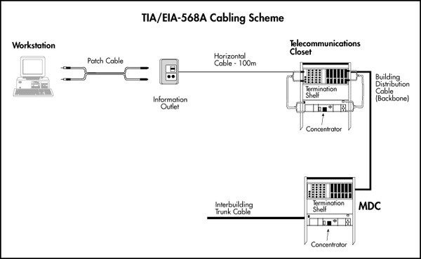
Cabling between utility closets and workstation locations shall be made as individual home runs. No intermediate splices or adapters (couplings) may be installed or utilized between the utility closet and the communications outlet at the workstation location. Riser cabling between utility closets and the building telecommunications entrance facility shall be made as individual home runs. No intermediate splices are permitted between the utility closets and the building telecommunications entrance facility. Individual building cables connect to the main optic fiber trunk cable at fusion splices in communications vaults.

4.2 Concealed Cabling
All cabling types shall be installed inside walls or ceiling spaces wherever possible. Any exposed cable run of more than three feet must be enclosed in appropriate raceway, as described below.
4.2.1 Raceways
Cable that can not be run inside a protected space must be enclosed in protective raceway such as Wiremold 400, 800, 2300 or Panduit type L. Protective raceways must be permanently attached to underlying wall surfaces with appropriate wall anchors.
4.2.2 Wall Penetrations
Cable penetrations of walls or floors designed as fire barriers are to be sleeved with metallic conduit or National Fire Protection Association (NFPA) approved flame-retardant innerduct and packed with fire blocking material in compliance with national, campus, and District of Columbia fire codes.
4.3 Maximum Lengths
4.3.1 Workstation Cable
The maximum length of any workstation cable run shall not exceed 90 meters (295 feet).
4.3.2 Riser Cable
The maximum length of any riser cable shall not exceed 500 meters (1,640 feet).
4.3.3 Interbuilding Cable
The maximum length of any multimode interbuilding cable shall not exceed 1,500 meters (4,920 feet). The maximum length of any single mode interbuilding cable shall not exceed 2,500 meters (8,200 feet).
4.3.4 Maximum Circuit Length
The maximum circuit length between the main campus optic fiber cross-connect point and any utility closet shall be 2,000 meters (6,555 feet) for multimode optic fiber cable and 3,000 meters (9,833 feet) for single mode optic fiber cable.
4.4 Securing Cables
All cables shall be dressed neatly and physically secured to prevent accidental dislocation or damage. It is not permissible to secure cabling to the outside of conduit or to gas, plumbing, steam, or any other functional pipes. Cables shall not be secured to any utility structures in any fashion that might prevent maintenance of or access to those facilities.
Since modern optic fiber cabling must be expected to carry high data rates, it is necessary to avoid stressing the optic fibers. Tight 90-degree bends are not permissible, and any tie-wraps or other securing straps must not be cinched tight. Care should be taken to avoid routing cables within 18 inches of heat generating devices such as electrical transformers or steam pipes.
5. Cable Termination
New optic fiber cables shall be terminated on color-coded 568SC connectors inside color-coded 568SC adapter patch panels in the utility closets, in building telecommunications entrance facilities, and in communications outlets at workstation locations. A 568SC connector consists of two color coded SC-type connectors joined to form a mated duplex pair. Beige colored connectors and adapters are specified for 62.5/125 micron multimode optic fiber. Blue colored connectors and adapters are specified for 8-10/125 micron single mode optic fiber.
5.1 Cross Connect Facilities
The following optic fiber coupling devices and associated materials are specified for use on the GW campus.
5.1.1 Building Telecommunications Entrance Facility
AT&T LGX Fiber Optic Distribution Frame and associated component parts.
Seicor Fiber Distribution Center (FDC) series and associated components.
5.1.2 Utility Closet Cross Connect
AT&T Fiber Optic Interconnection Units (LIUs) and associated component parts.
Siecor Wall Mounted Interconnection Center (WIC) series and associated components.
5.1.3 Associated Materials
NFPA approved optic fiber innerduct Panduit E3X3LG6 Type E wiring duct
Panduit C3LG6 Duct cover
5.2 Communications Outlets (CO's)
Each cable shall be terminated at the workstation location on the specified communications outlet.
5.2.1 Specifications
The specified communications outlets have spaces for multiple adapter inserts. Normally, one voice adapter will be placed in the topmost position and one data adapter will be placed below the voice adapter. The third position from the top is reserved for optic fiber use. A blank insert shall be installed in all unused spaces.
ISS has standardized on the use of the Ortronics communications outlet for most campus installations. Products from AT&T (Lucent) and Siemon are offered as substitutes. Clearance must be obtained from the Director of Technology - ISS, (202) 994-6005, prior to the installation of outlets other than the Ortronics product. Communications outlets for installation at GW shall consist of the following components.
5.2.1.1 Flush Mount
For flush mounting in recessed wall boxes use:
5.2.1.1.1 Ortronics
Ortronics OR-40300158 Face Plate
5.2.1.1.2 AT&T (Lucent)
AT&T M-Series Information Outlet
5.2.1.1.3 Siemon
Siemon CT4-FP-02 Single Gang Face Plate or
Siemon CT8-FP-02 Double Gang Face Plate
5.2.1.2 Surface Mount
For surface mounting use either:
5.2.1.2.1 Ortronics
Ortronics OR-40400028 Surface mount interface box
5.2.1.2.2 AT&T (Lucent)
AT&T M102SMB-262 Modular duplex surface mount box
AT&T M104SMB-262 Modular quadplex surface mount box
AT&T 40A1 Multimedia Information Outlet
5.2.1.2.3 Siemon
Siemon CT4-FP-02 Single Gang Face Plate or
Siemon CT8-FP-02 Double Gang Face Plate
5.2.2 Location
Where possible, the communications outlet shall be located so that its centerline is 18 inches above floor level or 12 inches above permanent bench surfaces. In no case shall it be installed lower than 12 inches above floor level without prior written approval from the Director of Technology - ISS, (202) 994-6005. Surface mounted outlets are acceptable if well secured. Recessed outlets require metal mounting boxes in any wall designated as a fire barrier.
Outlets shall not be mounted on temporary, movable, or removable surfaces, doors, or access hatches.
5.2.3 Adapter Inserts
A variety of inserts are available to make the specified communications outlets usable for different wiring applications. For all installations, unless specified otherwise, the default installed insert shall be the one designated as 568SC (duplex SC). It is critical that only those specified below be used.
5.2.3.1 Ortronics
Ortronics OR-60900044 1-Duplex SC Adapter Module
Ortronics OR-60900084 2-Duplex SC adapter modules
Ortronics OR-40300164 Blank Module
5.2.3.2 AT&T (Lucent)
Until an SC adapter is available use:
AT&T M81M-262 Single Modular Coupling Mounting Module
AT&T C20000A-2 ST Connector Coupling
5.2.3.3 Siemon
Siemon CT-A-SC-SC-80 Angled Fiber Coupler
Siemon CT-BLNK-02 Blank
5.3 Utility Closet Station Cable Termination
In the utility closet all optic fiber cables shall be terminated on wall-mounted patch panels or on patch panels mounted in standard 19-inch equipment racks. Where necessary, a new 3/4" plywood panel shall be firmly anchored to the wall to accommodate mounting of patch panels. Patch panels shall be located adjacent to any existing voice and data wiring patch panels. If no existing patch panels are present, a new location shall be chosen away from telephone blocks, cross-connects, and equipment. The proposed locations of patch panels or equipment racks must be approved by the Director of Technology - ISS, (202) 994-5006 before installation begins.
Each cable shall be left with a service loop (slack) of approximately twelve inches at the patch panel to facilitate future changes or connector retermination.
At the patch panel, it is imperative that the optic fiber outer protective sheath be maintained into the entrance of the patch panel. Only the minimum amount of sheath shall be removed at each connection point. There shall never be more than twelve inches of unsheathed optic fiber cable at either the wiring closet or workstation termination location.
5.4 Cross-Connects
In the communications closet and at the building telecommunications entrance facility indoor rated jumper cordage shall be used to run between electronic equipment and termination cabinets and for cross-connecting within a termination cabinet. Cordage is not suited for long conduit runs nor any type of outdoor use. Installed optic fiber jumper cable shall be of sufficient length to reach any port of the active electronics with a minimum of 8 inches slack after routing.
6. Labeling
Each individual cable and communications outlet shall be labeled. Cable labels shall be made with permanent black ink on laminated white labels between 6 and 9 inches from the cable ends. The label information shall consist of the room number of the workspace end, with a dashed suffix distinguishing multiple outlets in the same room. Thus, the first connection in room 245 would be labeled "245-1", the next as "245-2", and so on. The numbering suffix within a room should be initiated with xxxx-1 at the first communications outlet to the left of the entrance door and serialized in a clock-wise manner within the room. Installers should check with ISS staff for the next available suffix in room where existing cables are located. If there is only a single connection in a given room, it is to be labeled "xxxx-1", in anticipation of future expansion.
In the wiring closets, each 568SC adapter is to be labeled on the designation strips and on the cable jacket with an appropriate, permanently attached, label using the same scheme as above.
The workstation end of each cross-connect cable shall be labeled approximately 6 inches from it's terminal end. The label's information shall be identical to that on the 568SC adapter designation strip.
7. Compliance Testing
7.1 General
Optic fiber cabling is currently used for FDDI backbone and FORL Ethernet applications. ISS requires that all fibers of installed multimode and single mode optic fiber cables be tested for full compliance with specifications regardless of intended use. Contractors are required to provide written documentation of test results for all fibers of each cable. Documentation of test results must include all parameters listed below and be recorded on standard ISS Cable Test Sheets or provided on a ISS provided diskette in Microsoft Excel or Borland Paradox. Contact the Director of Technology - ISS, (202) 994-6005, for appropriate Cable Test Sheets and/or diskette.
7.2 Testing Strategy
After installation all cables shall be tested for distance and optical attenuation.
7.2.1 Workstation Cable
Tests shall be run from the utility closet 568SC adapter through the installed communications outlet 568SC adapter at the workspace end of the cable. The test shall include the fiber run and SC connectors inside 569SC adapters on both ends.
7.2.2 Riser Cable
Tests shall be run from the building telecommunications entrance facility 568SC adapter through the riser cable to the 568SC adapter in the utility closet. The test shall include the fiber run and SC connectors inside 569SC adapters on both ends.
7.2.3 Interbuilding Cable
Tests shall be run from the main campus cross-connect 568SC adapter through the campus backbone optic fiber to each building telecommunications entrance facility 568SC adapter. The test shall include the fiber run and SC connectors inside 569SC adapters on both ends.
7.3 Testing Parameters
All optic fibers shall meet or exceed the following specifications. Any cable not meeting or exceeding the following shall be inspected for anomalies, and replaced if necessary to ensure compliance.
* Workstation cable length shall not exceed 90 meters (295 feet).
* Building Riser cable length shall not exceed 500 meters (1,640 feet).
* Multimode interbuilding cable length shall not exceed 1,500 meters (4,920 feet).
* Single mode interbuilding cable length shall not exceed 2,500 meters (8,200 feet).
* Cable attenuation of multimode fiber shall be less than or equal to 1.5 dB/km at 1300nm.
* Cable attenuation of single mode fiber shall be less than or equal to 0.7 dB/km.
* Maximum loss for mated SC connectors is 0.75 dBs.
* Maximum loss for fusion or mechanical splices is 0.3 dBs.
8. Exceptions
Any exceptions to the above specifications must be approved in writing by the Director of Technology - ISS, (202) 994-5006 before work begins.
Data communication cabling specifications and usage are dynamic in nature. ISS reserves the right to change specifications and practices as changes in technology warrant. It is incumbent upon cable installers to check with ISS prior to planning and installation to ensure that current specifications and practices are understood and met.
Requests for clarification or exceptions to these specifications are to be directed to the Director of Technology - ISS, (202) 994-6005.
Created 03/03/1997 by Donald L. Steward, Ed. D., R.C.D.D.
![]() Send
comments to: dsteward@iun.edu
Send
comments to: dsteward@iun.edu
